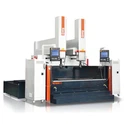
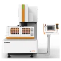
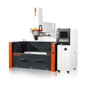
(1) The selection of cutting parts in wire cutting often leads to machining deformation, which affects machining accuracy and in severe cases, can result in workpiece scrapping. The main reason for workpiece deformation is the redistribution of internal stress present in the workpiece during online cutting processing. In order to reduce workpiece deformation, it is necessary to consider the cutting position of the workpiece in the billet, and reasonably select the cutting starting point, threading hole position, and cutting route. During wire cutting, there is significant deformation at the edges and corners of the billet (especially in quenched steel and hard alloys with poor heat treatment performance). Therefore, when selecting the cutting position and cutting route, it is advisable to avoid the edges and corners of the billet as much as possible, so that the cutting trajectory is evenly spaced from each small inch
(2) When selecting a cutting route, the workpiece should have good rigidity throughout the entire cutting process as much as possible. Generally, the cutting section that separates the workpiece from its clamping part is arranged for rear cutting to reduce workpiece deformation. In actual processing, in order to maintain the rigidity of the workpiece, sometimes the method of cutting while clamping is used, such as using glue to bond the workpiece during processing.
(3) The selection of the cutting starting point is generally also the cutting end point, but when the molybdenum wire returns to the starting point, there will inevitably be repeated positional errors, causing machining marks and affecting cutting accuracy and surface quality. Therefore, a reasonable selection of machining starting points should be made: ① cutting starting points should be selected on surfaces with lower surface roughness requirements; ② The cutting starting point should be selected as much as possible at the intersection point of the cutting pattern. For workpieces without cutting intersection points, the cutting starting point should be selected as much as possible in a location that is convenient for the fitter to recover. For surfaces with large radii and outer contours, it is important to avoid selecting surfaces with concave surfaces.
(4) The selection of threading hole position can use threading hole to cut the workpiece, which can keep the billet intact, thereby helping to maintain stiffness and reduce workpiece deformation. After determining the cutting starting point, the position of the threading hole can be determined. Generally, the threading hole is processed near the cutting starting point, at the intersection of trajectories or coordinate points that are easy to calculate. The diameter should not be too large or too small, and it is generally selected within the range of 3-10 millimeters.
When cutting two or more workpieces on the same blank, it is not possible to set only one threading hole to cut all workpieces at once. When processing large workpieces, multiple threading holes should be set on the machining trajectory to allow for re threading in case of wire breakage during cutting. When cutting workpieces with closed holes, the threading hole should be located inside the hole to be cut, which is easy to calculate and operate, but the unnecessary cutting stroke is longer. For large hole workpieces, threading holes should be located at the corners near the machining trajectory. When cutting the shape, the threading hole can be located on the outer edge of the profile, close to the cutting starting point. When cutting narrow grooves, threading holes should be set at the width of the pattern.